PreonLab
Piston Cooling Jet

July 22, 2021
Loïc Wendling, Jennifer Weiche, Shreyas Joshi and Aju Abraham

Piston Cooling Jets (PCJs) are used in traditional Internal Combustion (IC) engines to remove the excess heat from the piston, allowing for higher thermal loads to be reached. PreonLab 5.0 allows for investigations of the dynamic and thermal interactions between the lubricating oil jet and the moving piston.

Share:

Workflow

The simulation pipeline from the CAD model to the results is described in Figure 1. First, the “.stl” files and kinematics are imported into PreonLab. Then come the standard setup and the specific parametrization. PCJ problems require high resolutions to capture properly the oil jet impinging on the surface underneath the piston and therefore can benefit from the highly parallelized implementation of PreonLab. Once the simulation is done, the post-processing step will provide the insights you are seeking. The wide variety of sensors available enables you to study the various aspects of the problem and draw meaningful connections.

Figure 1: Overview of the simulation workflow

Setup

The piston considered is used in a V8 engine (see Figure 2) where pistons are positioned in a Vee configuration, maintaining an angle of 90° between them. The parameters are summarized in Table 1. Since only the relevant portion of the domain is discretized, you can easily import more objects to ascertain the position of the key components, here: the piston, the pin, and the nozzle.

Figure 2: Engine overview

Table 1: Engine specifications

Piston Motion

The pistons are imported and placed considering the engine geometry and the installation angle as seen in Figure 3. The piston motion is defined at a 1° Crank Angle (CA) interval for the first 360° CA (2 strokes). The looping function of PreonLab is then used to easily repeat the defined motion for the subsequent strokes. The resulting keyframes are shown in Figure 4.

Figure 3: Pistons installed in the engine and imported into PreonLab

Figure 4: Piston motion keyframing. The grey line is the piston position set by the user and the yellow line is the piston position set by PreonLab using the keyframe loop feature.

Fluid Inlet and Material Properties

The inlet boundary condition is placed at the end of the nozzle geometry, as shown in Figure 5 with a continuous inlet flow rate defined. The material properties of the oil used, 0W30, are presented in Table 2. With thermodynamics enabled, PreonLab will continually adjust the fluid properties of the oil per particle based on the local temperature. This is an important phenomenon to capture as viscosity typically exhibits a non-linear relationship with temperature.

Figure 5: Inlet boundary condition

Refinement Regions

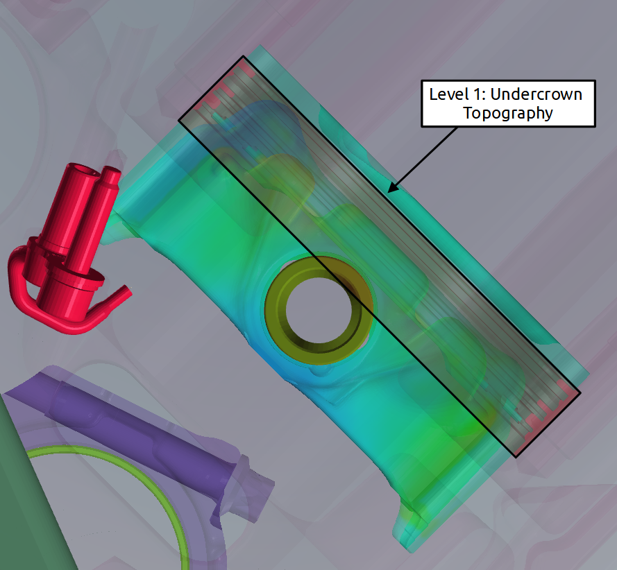
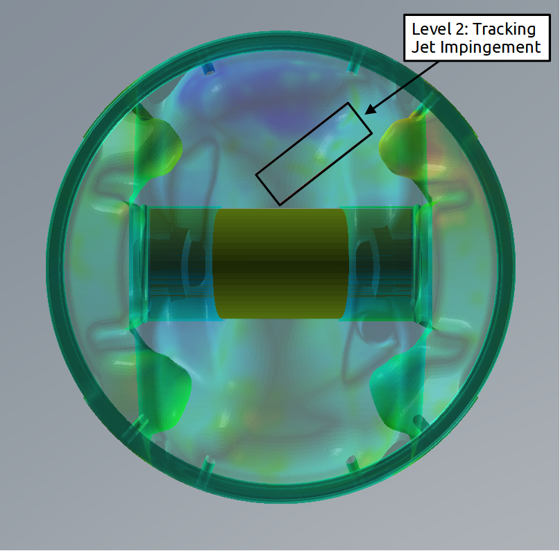
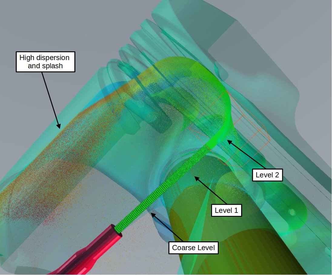
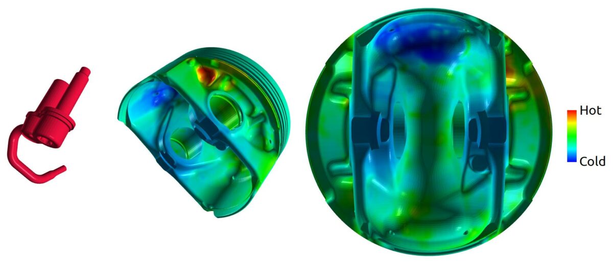
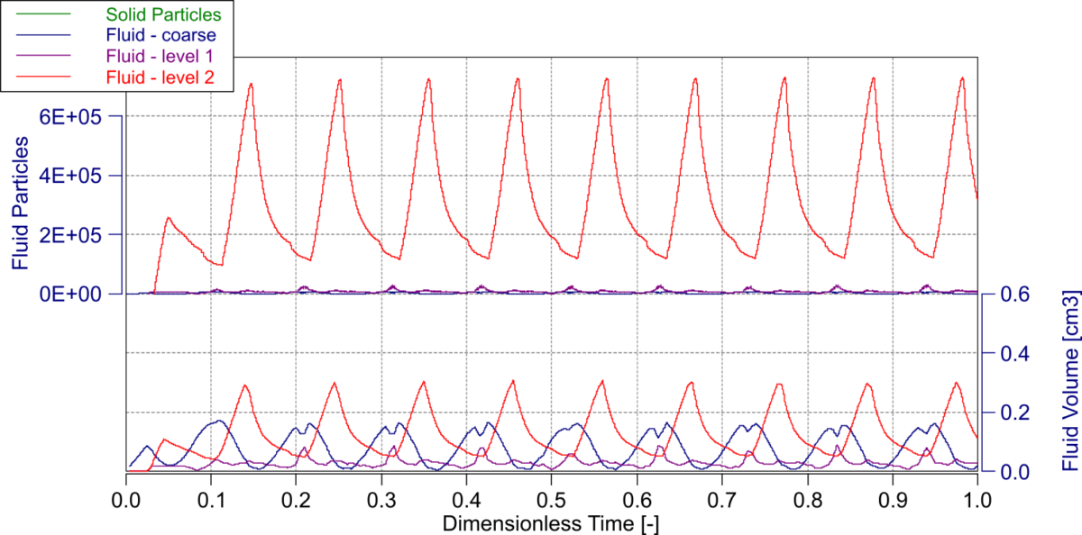
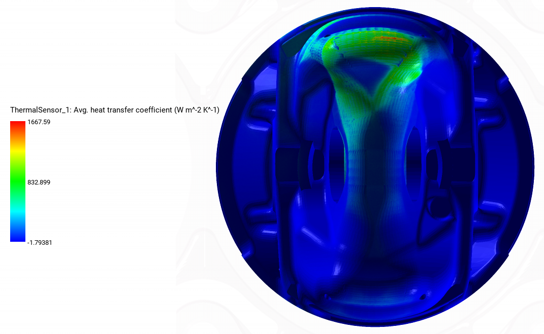
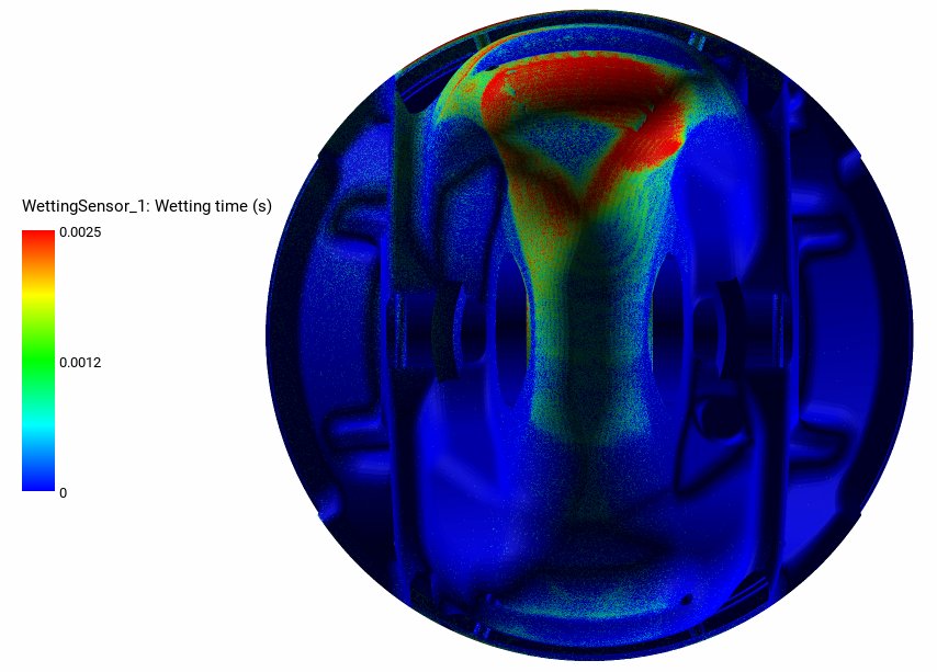
The improved refinement region feature allows you to dynamically adapt the particle spacing in key areas of the domain. In the case of the piston cooling jet application, the important region lies underneath the piston and in particular, special care needs to be given to the jet impingement point. Three levels of refinement are now available (coarse level, level 1, and level 2) with a respective spacing of 300, 150, and 75 µm. The spacing in SPH corresponds to the resolution of the numerical method. It is equivalent to choosing the element size when creating a mesh. Level 1 is used on the area underneath the piston where high heat transfer is expected (see Figure 6). In Figure 7, the level 2 refinement zone is shown and it is designed to follow the impingement point as it moves over the surface of the piston due to the nozzle angle. The difference in particle spacing between the different refinement levels can be seen in Figure 8.

Figure 6: Location of the level 1 refinement

Figure 7: Location of the level 2 refinement

Figure 8: The particles of the oil jet are refined as they rise through the crankcase. Once the oil falls back toward the sump, high particle dispersion can be observed.

Mapped Steady Temperature Boundary

For the thermal boundary condition, the temperature distribution underneath the piston is imported and set as the temperature boundary condition for the fluid simulation (see Figure 9). It allows you to have a realistic boundary condition and gives confidence in the resulting heat transfer coefficient.

Figure 9: Temperature map used as the temperature boundary condition.

Results

Workflow Statistics

To get a general estimate of the time needed to process the entire test case, a breakdown of the time spent on each step is summarized in Table 2. The breakdown shows that the labor-intensive pre-processing steps are kept to a minimum, while the computationally intensive simulation and post-processing steps take up most of the time. This approach frees up your time to prepare and investigate further simulations.

Table 2: Statistics of the PreonLab workflow.

The fluid volume per solver (middle plot in Figure 10) confirms that the coarse and level 1 refinement represent a good fraction of the fluid volume despite having a low particle count (top plot in Figure 10). This demonstrates that the bulk of the computational effort is spent in high-resolution areas of interest.

Figure 10: Particle count and volume for each refinement level together with the number of solid particles. The Level 2 refinement (finest level) carries 80% of the particle count and 20% of the fluid volume.

Spray Pattern

In the video hereafter, the spray pattern can be seen from two angles (Video 1 and 2). It also shows clearly the interaction between the oil jet and the piston. In this example, a break in contact between the oil jet and the crown as the piston approaches TDC. Adjusting flow rate or jet outlet velocity could mitigate this effect and ensure continuous cooling. The downstroke, on the other hand, is more promising with the oil spreading over the piston surface at high speed which is desired for optimal heat removal.

Please agree to the transfer of data to third parties as set out in our privacy policy.

Video 1: Spray pattern from the front angle (1/200x playback speed)

Please agree to the transfer of data to third parties as set out in our privacy policy.

Video 2: Spray pattern from the side angle (1/200x playback speed)

Heat Transfer Coefficient Distribution

The behavior observed in the previous section is confirmed by the Heat Transfer Coefficient (HTC) distribution shown in Video 3. You can see that the highest HTC is around the jet impingement point. What is also captured well is the impingement point movement caused by the angle of the nozzle. PreonLab allows you to measure the time-averaged heat transfer coefficient on the piston undercrown (cf. Figure 11). For this application, it corresponds to a stroke-averaged heat transfer coefficient and informs you on the effective heat transfer between the PCJ and the piston.

Please agree to the transfer of data to third parties as set out in our privacy policy.

Video 3: Heat transfer coefficient over time (1/1000x playback speed)

Figure 11: Time-averaged heat transfer coefficient

Y+ Sensor

The y+ sensor provides the y+ value that is used to determine if the discretization (particle size) at the wall is small enough to capture the viscous effects at the wall. In Video 4, the y+ values do not exceed 20 which is within the linear region (viscous sublayer). In this region, no wall function is required.

Please agree to the transfer of data to third parties as set out in our privacy policy.

Video 4: Y+ value over time (1/1000x playback speed)

Cycle Average Wetting Time

The wetting time sensor measures how much time the fluid spent in contact with the wall. Gathered over time and for the entire surface, the result is shown in Figure 12. This wetting pattern is consistent with an impinging jet pattern which has high wetting time around the impingement point. The impingement point location and the piston geometry (there is a recess in the piston geometry as seen in Video 1) justifies the higher wetting time located on the top of the figure.

Figure 12: Wetting time at the end of the simulation

Fixed Flow Rate – Jet Sizing

After the first simulation, the effect of increasing one of the design parameters, the nozzle diameter, can be investigated. The wider nozzle has a diameter 1.5x bigger than the narrow orifice. The comments to the results seen in Figure 13 are:

  • The wider orifice for a fixed flow rate leads to a lower jet velocity and creates a delay in the surface wetting.
  • The same lower jet velocity leads to a lower surface average HTC.
  • In both cases, the average y+ is small enough that a wall function (law of the wall) need not be applied.
  • The effect of the reciprocating motion of the piston is visible on all the metrics.
  • The absence of a cooling gallery in the piston does not favor oil retention and therefore the system reaches rapidly a steady-state for HTC and wetting.

Figure 13: Surface area (wetted area in green), average HTC (in black), average y+ (in blue), and maximum y+ (in purple) for two nozzle sizes

PreonPy/ PreonLab Workflow for PCJs

Figure 14 shows the improved workflow that uses PreonPy to generate the scene files based on the design parameters. The scenes can then be processed in parallel on the cluster of your choice. The post-processing step extracts the expected metrics in a standardized format and can be done remotely or locally. From the gained insights, new operating points can be devised and input into the PreonPy script to generate new scenes to investigate. By this iterative procedure, the set of design parameters leading to the desired optimum (best cooling for example) can be found.

Figure 14: PreonPy with PreonLab workflow for PCJs

Conclusion

PreonLab has been successfully used for a complex oil jet non-gallery piston cooling application. Various relevant metrics have been post-processed and two design points have been compared. The PreonPy/PreonLab workflow can help expand the sensitivity study to more design parameters. The new features of PreonLab 5.0, enhanced thermal sensor and adaptive spacing, are especially suited for the constraints of piston cooling jet applications.

Please agree to the transfer of data to third parties as set out in our privacy policy.

Piston Cooling Jet Article

RELATED ARTICLES

LEARN MORE ABOUT PreonLab Updates

How to get started with
Preonlab CFD software?
Get in Touch